CONFIG ATEMU/de
Contents |
= (**COPIED FROM ENGLISH PAGE**) === Action
Configures the PS/2 keyboard data and clock pins.
Syntax
CONFIG ATEMU = int , DATA = data, CLOCK=clock [,INIT=VALUE]
Remarks
|
Int |
The interrupt used such as INT0 or INT1. |
|
DATA |
The pin that is connected to the DATA line. This must be the same pin as the used interrupt. |
|
CLOCK |
The pin that is connected to the CLOCK line. |
|
INIT |
An optional value that will identify the keyboard. By default or when omitted this is &HAB83. The code that identifies a keyboard. Some mother boards/BIOS seems to require the reverse &H83AB. By making it an option you can pass any possible value. The MSB is passed first, the LSB last. |
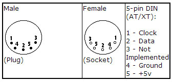
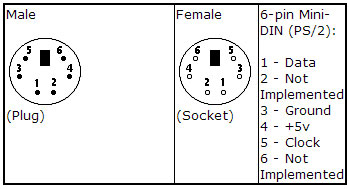
Old PC’s are equipped with a 5-pin DIN female connector. Newer PC’s have a 6-pin mini DIN female connector.
The male sockets must be used for the connection with the micro.
Besides the DATA and CLOCK you need to connect from the PC to the micro, you need to connect ground. You can use the +5V from the PC to power your microprocessor.
The config statement will setup an ISR that is triggered when the INT pin goes low. This routine you can find in the library.
The ISR will retrieve a byte from the PC and will send the proper commands back to the PC.
The SENDSCANKBD statement allows you to send keyboard commands.
Note that unlike the mouse emulator, the keyboard emulator is also recognized after your PC has booted.
The PS2 Keyboard and mouse emulator needs an additional commercial addon library.
See also
Example
'-----------------------------------------------------------------------------------------
'name : ps2_kbdemul.bas
'copyright : (c) 1995-2005, MCS Electronics
'purpose : PS2 AT Keyboard emulator
'micro : 90S2313
'suited for demo : no, ADD ONE NEEDED
'commercial addon needed : yes
'-----------------------------------------------------------------------------------------

$regfile = "2313def.dat" ' specify the used micro
$crystal = 4000000 ' used crystal frequency
$baud = 19200 ' use baud rate
$hwstack = 32 ' default use 32 for the hardware stack
$swstack = 10 ' default use 10 for the SW stack
$framesize = 40 ' default use 40 for the frame space

$lib "mcsbyteint.lbx" ' use optional lib since we use only bytes

'configure PS2 AT pins
Enable Interrupts ' you need to turn on interrupts yourself since an INT is used
Config Atemu = Int1 , Data = Pind.3 , Clock = Pinb.0
' ^------------------------ used interrupt
' ^----------- pin connected to DATA
' ^-- pin connected to clock
'Note that the DATA must be connected to the used interrupt pin


Waitms 500 ' optional delay

'rcall _AT_KBD_INIT
Print "Press t for test, and set focus to the editor window"
Dim Key2 As Byte , Key As Byte
Do
 Key2 = Waitkey() ' get key from terminal
 Select Case Key2
 Case "t" :
 Waitms 1500
 Sendscankbd Mark ' send a scan code
 Case Else
 End Select
Loop
Print Hex(key)

Mark: ' send mark
Data 12 , &H3A , &HF0 , &H3A , &H1C , &HF0 , &H1C , &H2D , &HF0 , &H2D , &H42 , &HF0 , &H42
' ^ send 12 bytes
' m a r k
| Languages | English • Deutsch |
|---|

