Using the UART/de
m (1 revision) |
(→(**COPIED FROM ENGLISH PAGE**) =) |
||
| Line 1: | Line 1: | ||
| − | + | = <span class="f_Header">UART</span> = | |
| − | + | Ein Universal Asynchronous Receiver and Transmitter (UART) kann benutzt werden um Daten zwischen zwei Geräten zu senden und zu empfangen. Diese zwei Geräte können sein: PC-zu-PC, PC-zu-Mikrocontroller oder Mikrocontroller-zu-Mikrocontroller. Die UART Kommunikation benutzt TTL Spannungen von +5V and 0V oder LVTTL abhängig von der Mikrocontroller Betriebsspannung. | |
| | ||
| − | + | Wenn eine Verbindung zum PC gewünscht wird dann muss das RS232-Protokoll verwendet werden. Das bedeutet, dass mit definierten Spannungen (+15V und -15V) kommuniziert werden muss. Die kann mit einem MAX232 Level-Shifter erreicht werden. | |
| | ||
| − | + | Die Hardware wird im folgenden Schaltplan dargestellt: | |
<span style="font-family: Arial;"> </span> | <span style="font-family: Arial;"> </span> | ||
| Line 17: | Line 17: | ||
<span style="font-family: Arial;"> </span> | <span style="font-family: Arial;"> </span> | ||
| − | + | Der DB-9 Anschluss hat 9 Pins aber es müsse nur 3 davon benutzt werden. Die obige Grafik zeigt die Vorderansicht - gelötet wird auf der anderen Seite. Bei den meisten Anschlüssen sind die Pinbezeichnungen auch auf den Steckern und Buchsen selbst zu lesen. | |
| | ||
| − | + | Wenn der verwendete Mikrocontroller HW-UART nicht unterstützt dann kann auch Software-UART benutzt werden. Siehe unten. Wenn der Mikrocontroller einen HW-UART unterstützt dann werden die TxD und RxD Pins mit TxD und RxD im Schaltplan verbunden. Wenn der Mikrocontroller mehrere HW-UARTs hat dann werden die TxD0 und RxD0 Pins mit TxD und RxD entsprechend obigem Schaltplan verbunden. | |
| − | + | Nun muss per Programm der Mikrocontroller initialisiert werden. Öffnen Sie dazu eine neue .bas Datei und fügen Sie die folgenden Programmzeilen am Anfang hinzu. | |
| | ||
| − | <span style="font-family: Courier; font-weight: bold; color: rgb(0, 0, 128);">$regfile</span><span style="font-family: Courier;"> </span><span style="font-family: Courier; color: rgb(255, 0, 0);">=</span><span style="font-family: Courier;"> </span><span style="font-family: Courier; color: rgb(0, 128, 128);">" | + | <span style="font-family: Courier; font-weight: bold; color: rgb(0, 0, 128);">$regfile</span><span style="font-family: Courier;"> </span><span style="font-family: Courier; color: rgb(255, 0, 0);">=</span><span style="font-family: Courier;"> </span><span style="font-family: Courier; color: rgb(0, 128, 128);">"verwendeter_mikrocontroller def.dat"</span> |
<span style="font-family: Courier; font-weight: bold; color: rgb(0, 0, 128);">$crystal</span><span style="font-family: Courier;"> </span><span style="font-family: Courier; color: rgb(255, 0, 0);">=</span><span style="font-family: Courier;"> 8000000</span> | <span style="font-family: Courier; font-weight: bold; color: rgb(0, 0, 128);">$crystal</span><span style="font-family: Courier;"> </span><span style="font-family: Courier; color: rgb(255, 0, 0);">=</span><span style="font-family: Courier;"> 8000000</span> | ||
| Line 35: | Line 35: | ||
<span style="font-family: Arial;"> </span> | <span style="font-family: Arial;"> </span> | ||
| − | + | Stellen Sie sicher, dass der benutzte Mikrocontroller mit $regfile angegeben wird - zum Beispiel der ATMega32 | |
<span style="font-family: Courier; font-weight: bold; color: rgb(0, 0, 128);">$regfile</span><span style="font-family: Courier;"> </span><span style="font-family: Courier; color: rgb(255, 0, 0);">=</span><span style="font-family: Courier;"> </span><span style="font-family: Courier; color: rgb(0, 128, 128);">"m32def.dat"</span> | <span style="font-family: Courier; font-weight: bold; color: rgb(0, 0, 128);">$regfile</span><span style="font-family: Courier;"> </span><span style="font-family: Courier; color: rgb(255, 0, 0);">=</span><span style="font-family: Courier;"> </span><span style="font-family: Courier; color: rgb(0, 128, 128);">"m32def.dat"</span> | ||
| Line 41: | Line 41: | ||
<span style="font-family: Arial;"> </span> | <span style="font-family: Arial;"> </span> | ||
| − | + | Einige Mikrocontroller können einen internen Oszillator als Taktquelle verwenden. Einige Mikrocontroller verwenden den internen Oszillator standardmäßig. Bei Benutzung eines internen Oszillators braucht man keinen (externen) Quarz. | |
| | ||
| − | <span style="font-family: Arial; font-weight: bold; color: rgb(255, 0, 0); text-decoration: underline;"> | + | <span style="font-family: Arial; font-weight: bold; color: rgb(255, 0, 0); text-decoration: underline;">Führen Sie diesen Schritt nur aus wenn Sie einen internen Oszillator verwenden.</span> |
| − | + | Öffnen Sie den BASCOM-AVR Programmer wie folgt: | |
| Line 58: | Line 58: | ||
|- valign="baseline" style="vertical-align: baseline;" | |- valign="baseline" style="vertical-align: baseline;" | ||
| width="13" | <span style="font-size: 10pt; font-family: 'Arial Unicode MS', 'Lucida Sans Unicode', Arial;">•</span> | | width="13" | <span style="font-size: 10pt; font-family: 'Arial Unicode MS', 'Lucida Sans Unicode', Arial;">•</span> | ||
| − | | | + | | Wählen Sie den “Lock and Fuse Bits” Tab aus und and maximimieren Sie das Programmer-Fenster. |
|} | |} | ||
</div><div style="padding: 0px; margin: 0px -84px 0px 11px;"> | </div><div style="padding: 0px; margin: 0px -84px 0px 11px;"> | ||
| Line 64: | Line 64: | ||
|- valign="baseline" style="vertical-align: baseline;" | |- valign="baseline" style="vertical-align: baseline;" | ||
| width="13" | <span style="font-size: 10pt; font-family: 'Arial Unicode MS', 'Lucida Sans Unicode', Arial;">•</span> | | width="13" | <span style="font-size: 10pt; font-family: 'Arial Unicode MS', 'Lucida Sans Unicode', Arial;">•</span> | ||
| − | | | + | | Prüfen Sie, ob Sie den folgenden “Fusebit” Abschnitt sehen: |
|} | |} | ||
</div> | </div> | ||
"1:Divide Clock by 8 Disabled" | "1:Divide Clock by 8 Disabled" | ||
| − | | + | und |
"Int. RC Osc. 8 MHz; Start-up time: X CK + X ms; [CKSEL=XXXX SUT=XX]" | "Int. RC Osc. 8 MHz; Start-up time: X CK + X ms; [CKSEL=XXXX SUT=XX]" | ||
| Line 79: | Line 79: | ||
<span style="font-family: Arial;"> </span> | <span style="font-family: Arial;"> </span> | ||
| − | + | Diese Einstellungen gibt es nicht bei jedem AVR Mikrocontroller. Wenn Sie die Einträge bei sich nicht haben dann ändern Sie nicht irgendwelche Fuse Bits. | |
| + | |||
| | ||
| − | + | Wenn diese Einstellungen verfügbar sind aber mit anderen Werten dann ändern Sie die Werte durch die Drop Down Möglichkeiten. Schließlich klicken Sie den "Program FS" Knopf und dann "Refresh" um die tatsächlichen Einstellungen zu sehen. | |
| | ||
| − | + | Verbinden Sie nun Mikrocontroller und PC mit einem Kabel mit DB-9 Anschluss | |
| + | |||
| + | Schreiben Sie ein Testprogramm für Ihren Mikrocontroller welches folgendermaßen aussehen sollte: | ||
| − | |||
| | ||
| − | <span style="font-family: Courier; font-weight: bold; color: rgb(0, 0, 128);">$regfile</span><span style="font-family: Courier;"> </span><span style="font-family: Courier; color: rgb(255, 0, 0);">=</span><span style="font-family: Courier;"> </span><span style="font-family: Courier; color: rgb(0, 128, 128);">"m32def.dat"</span><span style="font-family: Courier;"> </span><span style="font-family: Courier; color: rgb(0, 128, 0);">' | + | <span style="font-family: Courier; font-weight: bold; color: rgb(0, 0, 128);">$regfile</span><span style="font-family: Courier;"> </span><span style="font-family: Courier; color: rgb(255, 0, 0);">=</span><span style="font-family: Courier;"> </span><span style="font-family: Courier; color: rgb(0, 128, 128);">"m32def.dat"</span><span style="font-family: Courier;"> </span><span style="font-family: Courier; color: rgb(0, 128, 0);">'Verwendeter Mikrocontroller</span> |
<span style="font-family: Courier; font-weight: bold; color: rgb(0, 0, 128);">$crystal</span><span style="font-family: Courier;"> </span><span style="font-family: Courier; color: rgb(255, 0, 0);">=</span><span style="font-family: Courier;"> 8000000 </span> | <span style="font-family: Courier; font-weight: bold; color: rgb(0, 0, 128);">$crystal</span><span style="font-family: Courier;"> </span><span style="font-family: Courier; color: rgb(255, 0, 0);">=</span><span style="font-family: Courier;"> 8000000 </span> | ||
| Line 103: | Line 105: | ||
<span style="font-family: Courier; font-weight: bold; color: rgb(0, 0, 128);">Do</span> | <span style="font-family: Courier; font-weight: bold; color: rgb(0, 0, 128);">Do</span> | ||
| − | <span style="font-family: Courier; font-weight: bold; color: rgb(0, 0, 128);"> Print</span><span style="font-family: Courier;"> </span><span style="font-family: Courier; color: rgb(0, 128, 128);">" | + | <span style="font-family: Courier; font-weight: bold; color: rgb(0, 0, 128);"> Print</span><span style="font-family: Courier;"> </span><span style="font-family: Courier; color: rgb(0, 128, 128);">"Hallo Welt"</span> |
<span style="font-family: Courier; font-weight: bold; color: rgb(0, 0, 128);">Waitms</span><span style="font-family: Courier;"> 25</span> | <span style="font-family: Courier; font-weight: bold; color: rgb(0, 0, 128);">Waitms</span><span style="font-family: Courier;"> 25</span> | ||
| Line 115: | Line 117: | ||
<span style="font-family: Arial;"> </span> | <span style="font-family: Arial;"> </span> | ||
| − | + | Öffnen Sie nun Das BASCOM Terminal-Programm und stellen Sie die Verbindungseinstellungen unter “Terminal” -> “Settings” ein. Wählen Sie den Com-Port wie am PC und stellen Sie eine Baudrate ein von 19200, Parity none, Data bits 8, Stop bits 1, Handshake none, emulation none. | |
| | ||
| Line 123: | Line 125: | ||
<span style="font-family: Arial;"> </span> | <span style="font-family: Arial;"> </span> | ||
| − | + | Wenn Sie das "Hallo Welt" im BASCOM Terminal Emulator Fenster angezeigt bekommen dann ist alles in Ordnung. | |
| | ||
Revision as of 23:08, 25 February 2013
Contents |
UART
Ein Universal Asynchronous Receiver and Transmitter (UART) kann benutzt werden um Daten zwischen zwei Geräten zu senden und zu empfangen. Diese zwei Geräte können sein: PC-zu-PC, PC-zu-Mikrocontroller oder Mikrocontroller-zu-Mikrocontroller. Die UART Kommunikation benutzt TTL Spannungen von +5V and 0V oder LVTTL abhängig von der Mikrocontroller Betriebsspannung.
Wenn eine Verbindung zum PC gewünscht wird dann muss das RS232-Protokoll verwendet werden. Das bedeutet, dass mit definierten Spannungen (+15V und -15V) kommuniziert werden muss. Die kann mit einem MAX232 Level-Shifter erreicht werden.
Die Hardware wird im folgenden Schaltplan dargestellt:
Der DB-9 Anschluss hat 9 Pins aber es müsse nur 3 davon benutzt werden. Die obige Grafik zeigt die Vorderansicht - gelötet wird auf der anderen Seite. Bei den meisten Anschlüssen sind die Pinbezeichnungen auch auf den Steckern und Buchsen selbst zu lesen.
Wenn der verwendete Mikrocontroller HW-UART nicht unterstützt dann kann auch Software-UART benutzt werden. Siehe unten. Wenn der Mikrocontroller einen HW-UART unterstützt dann werden die TxD und RxD Pins mit TxD und RxD im Schaltplan verbunden. Wenn der Mikrocontroller mehrere HW-UARTs hat dann werden die TxD0 und RxD0 Pins mit TxD und RxD entsprechend obigem Schaltplan verbunden.
Nun muss per Programm der Mikrocontroller initialisiert werden. Öffnen Sie dazu eine neue .bas Datei und fügen Sie die folgenden Programmzeilen am Anfang hinzu.
$regfile = "verwendeter_mikrocontroller def.dat"
$crystal = 8000000
$baud = 19200
Stellen Sie sicher, dass der benutzte Mikrocontroller mit $regfile angegeben wird - zum Beispiel der ATMega32
$regfile = "m32def.dat"
Einige Mikrocontroller können einen internen Oszillator als Taktquelle verwenden. Einige Mikrocontroller verwenden den internen Oszillator standardmäßig. Bei Benutzung eines internen Oszillators braucht man keinen (externen) Quarz.
Führen Sie diesen Schritt nur aus wenn Sie einen internen Oszillator verwenden.
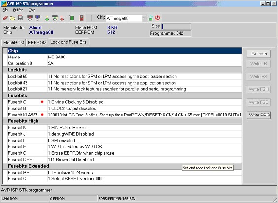
Öffnen Sie den BASCOM-AVR Programmer wie folgt:
| • | Wählen Sie den “Lock and Fuse Bits” Tab aus und and maximimieren Sie das Programmer-Fenster. |
| • | Prüfen Sie, ob Sie den folgenden “Fusebit” Abschnitt sehen: |
"1:Divide Clock by 8 Disabled"
und
"Int. RC Osc. 8 MHz; Start-up time: X CK + X ms; [CKSEL=XXXX SUT=XX]"
Diese Einstellungen gibt es nicht bei jedem AVR Mikrocontroller. Wenn Sie die Einträge bei sich nicht haben dann ändern Sie nicht irgendwelche Fuse Bits.
Wenn diese Einstellungen verfügbar sind aber mit anderen Werten dann ändern Sie die Werte durch die Drop Down Möglichkeiten. Schließlich klicken Sie den "Program FS" Knopf und dann "Refresh" um die tatsächlichen Einstellungen zu sehen.
Verbinden Sie nun Mikrocontroller und PC mit einem Kabel mit DB-9 Anschluss
Schreiben Sie ein Testprogramm für Ihren Mikrocontroller welches folgendermaßen aussehen sollte:
$regfile = "m32def.dat" 'Verwendeter Mikrocontroller
$crystal = 8000000
$baud = 19200
Do
Print "Hallo Welt"
Waitms 25
Loop
End
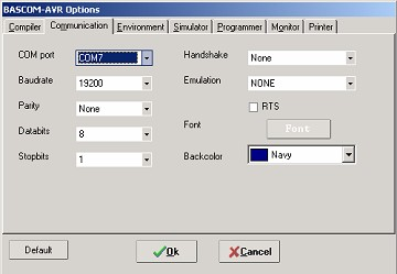
Öffnen Sie nun Das BASCOM Terminal-Programm und stellen Sie die Verbindungseinstellungen unter “Terminal” -> “Settings” ein. Wählen Sie den Com-Port wie am PC und stellen Sie eine Baudrate ein von 19200, Parity none, Data bits 8, Stop bits 1, Handshake none, emulation none.
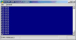
Wenn Sie das "Hallo Welt" im BASCOM Terminal Emulator Fenster angezeigt bekommen dann ist alles in Ordnung.
Example
You can also try this example with the BASCOM Terminal emulator, it shows you how to send and receive with various commands.
$regfile = "m88def.dat"
$crystal = 8000000
$baud = 19200
Dim Akey As Byte 'Here we declare a byte variable
Print "Hello, hit any alphanumerical key..."
Akey = Waitkey() 'Waitkey waits untill a char is received from the UART
Print Akey
Wait 1
Print "Thanks!, as you could see the controller prints a number"
Print "but not the key you pressed."
Wait 1
Print "Now try the enter key..."
Akey = Waitkey()
Akey = Waitkey()
Print Akey
Print "The number you see is the ASCII value of the key you pressed."
Print "We need to convert the number back to the key..."
Print 'Notice what this line does
Print "Please try an alphanumerical key again..."
Akey = Waitkey()
Print Chr(akey) 'Notice what this does
Print "That's fine!"
Wait 1
Print "For a lot of functions, just one key is not enough..."
Print "Now type your name and hit enter to confirm"
Dim Inputstring As String * 12 'Declare a string variable here
Do
Akey = Waitkey()
If Akey = 13 Then Goto Thanks 'On enter key goto thanks
Inputstring = Inputstring + Chr(akey) 'Assign the string
Loop
Thanks:
Print "Thank you " ; Inputstring ; " !" 'Notice what ; does
Wait 1
Print "Take a look at the program code and try to understand"
Print "how this program works. Also press F1 at the statements"
Print "If you understand everything continue to the next experiment"
End
ASCII
As you could have seen in the previous example we use the PRINT statement to send something to the UART. Actually we do not send just text. We send ASCII characters. ASCII means American Standard Code for Information Interchange. Basically ASCII is a list of 127 characters.
ASCII Table (Incomplete)
Decimal Hex Binary Value
------- --- ------ -----
000 000 00000000 NUL (Null char.)
008 008 00001000 BS (Backspace)
009 009 00001001 HT (Horizontal Tab)
010 00A 00001010 LF (Line Feed)
012 00C 00001100 FF (Form Feed)
013 00D 00001101 CR (Carriage Return)
048 030 00110000 0
049 031 00110001 1
052 034 00110100 4
065 041 01000001 A
066 042 01000010 B
067 043 01000011 C
You can find a complete ASCII table here
CARRIAGE RETURN (CR) AND LINE FEED (LF)
In the previous example you can also see that a second print statement always prints the printed text to the following line. This is caused by the fact that the print statement always adds the CR and LF characters.
Basically if we state:
Print “ABC”
We send 65 66 67 13 10 to the UART. (In binary format)
The carriage return character (13) returns the cursor back to column position 0 of the current line. The line feed (10) moves the cursor to the next line.
Print “ABC” ;
When we type a semicolon ( ; ) at the end of the line...
Bascom does not send a carriage return/line feed, so you can print another text after the ABC on the same line.
Print “ABC” ; Chr(13) ;
This would send only ABC CR. The next print would overwrite the ABC.
OVERVIEW
Here are some other commands that you can use for UART communications:
Waitkey()
Waitkey will until a character is received in the serial buffer.
Ischarwaiting()
Returns 1 when a character is waiting in the hardware UART buffer.
Inkey()
Inkey returns the ASCII value of the first character in the serial input buffer.
Sends a variable or non-variable string to the UART
ANOTHER EXAMPLE
This example shows how to use Ischarwaiting to test if there is a key pressed. And if there is, read to a variable.
'Print "Press B key to start"
Dim Serialcharwaiting As Byte, Serialchar As Byte
Serialcharwaiting = Ischarwaiting() 'Check if B or b pressed then goto
If Serialcharwaiting = 1 Then
Serialchar = Inkey()
If Serialchar = 66 Or Serialchar = 98 Then
Goto MyRoutine
End If
End If
Goto Main
Myroutine:
'Statements
Main:
'Statements
End
BUFFERING SERIAL DATA
If you wish to send and receive data at high speed, you need to use serial input and serial output buffers. This buffering is implemented in BASCOM-AVR and can only be used for hardware UART’s.
To configure a UART to use buffers, you need to use the Config statement.
Config Serialout = Buffered , Size = 20
and/or
Config Serialin = Buffered , Size = 20
More information can be found in BASCOM-Help. Search topic = "config serialin". There is also a sample program “RS232BUFFER.BAS” in the samples folder if you wish a demonstration of the buffering.
SOFTWARE UART
The previous examples used the hardware UART. That means the compiler uses the internal UART registers and internal hardware (RxD(0) and TxD(0)) of the AVR. If you don’t have a hardware UART you can also use a software UART.
The Bascom compiler makes it easy to “create” additional UART’s. Bascom creates software UART’s on virtually every port pin.
Remember that a software UART is not as robust as a hardware UART, thus you can get timing problems if you have lots of interrupts in your program.
For this example we use micro controller pins portc.1 and portc.2.
Connect portc.1 to TxD and portc.2 to RxD see the schematic above.
Change the $regfile and program this example:
$regfile = "m88def.dat"
$crystal = 8000000
$baud = 19200
Dim B As Byte
Waitms 100
'Open a TRANSMIT channel for output
Open "comc.1:19200,8,n,1" For Output As #1
Print #1 , "serial output"
'Now open a RECEIVE channel for input
Open "comc.2:19200,8,n,1" For Input As #2
'Since there is no relation between the input and output pin
'there is NO ECHO while keys are typed
Print #1 , "Press any alpha numerical key"
'With INKEY() we can check if there is data available
'To use it with the software UART you must provide the channel
Do
'Store in byte
B = Inkey(#2)
'When the value > 0 we got something
If B > 0 Then
Print #1 , Chr(b) 'Print the character
End If
Loop
Close #2 'Close the channels
Close #1
End
After you have programmed the controller and you connected the serial cable, open the terminal emulator by clicking on ![]() in Bascom.
in Bascom.
You should see the program asking for an alphanumerical input, and it should print the input back to the terminal.
| Languages | English • Deutsch |
|---|


